AN1176 APPLICATION NOTE
The SG3524 were designed for switching regulators of either polarity, transformer-coupled dc-to-dc converters, transformerless voltage doublers, and polarity-converter applications employing fixed-frequency, pulse-width modulation (PWM) techniques.
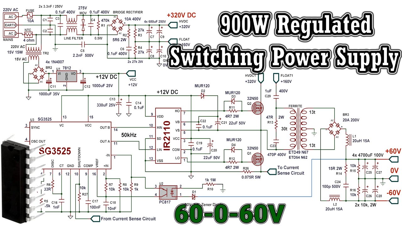
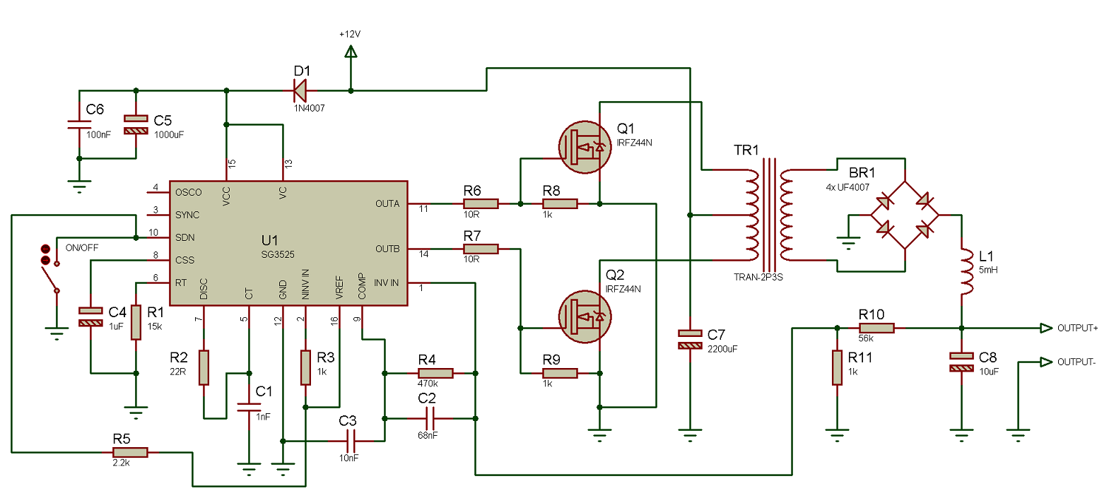
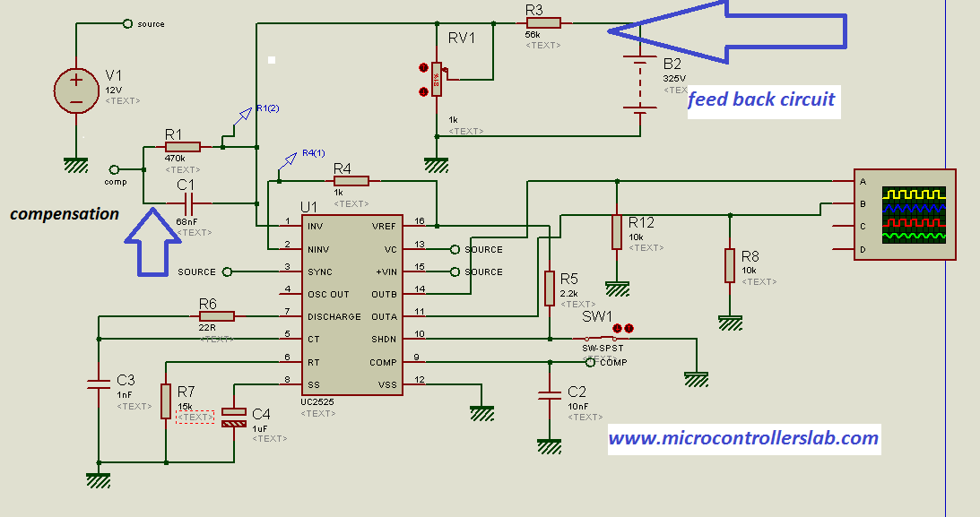
900W Regulated Switching Power Supply with SG3525 for High Power
App Notes; Deadband with the SG1524 Regulating PWM Circuit PS-3: Improving SG1524 Switching Regulator Dynamic Response PS-4: SG1524 Buck, Flyback, Push-Pull Application Note PS-2. SG3524; High-Reliability Military-grade Devices High-Reliability Power Management High-Reliability Isolated Switching Regulators; Power Management Drivers, High.
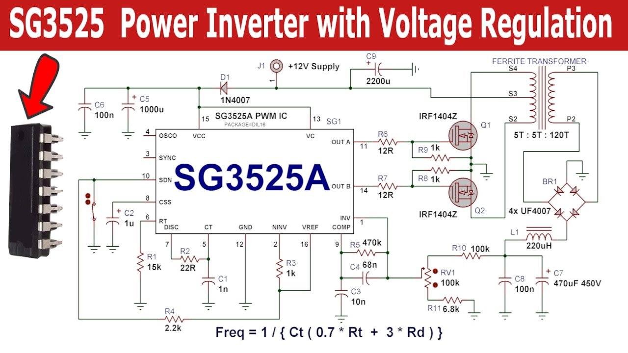
SG3525 PWM IC Pinout, Examples, Applications, Features, Datasheet
SG2524 and SG3524 were designed for switching regulators of either polarity, transformer-coupled dc-to-dc converters, transformerless voltage doublers, and polarity-converter applications employing fixed-frequency, pulse-width modulation (PWM) techniques. The complementary output allows either single-ended or push-pull application.

high voltage booster circuit
Pulse Width Modulator Control Circuit SG3525A The SG3525A pulse width modulator control circuit offers improved performance and lower external parts count when implemented for controlling all types of switching power supplies.
AN1348 APPLICATION NOTE
SG3524 Datasheet. Part #: SG3524. Datasheet: 125Kb/5P. Manufacturer: NXP Semiconductors. Description: SMPS control circuit. 60 Results. Datasheet: 93Kb/9P. Manufacturer: STMicroelectronics.

SG3524 Not able to achieve the output required Power management
signal to alternate between the two outputs. Note that for single-ended applications, the two outputs can be con-nected in parallel and the frequency of the output is the frequency of the oscillator. For push-pull applications, the outputs are separated and the action of the flip-flop pro-vides an output frequency ½ that of the oscillator. 3.
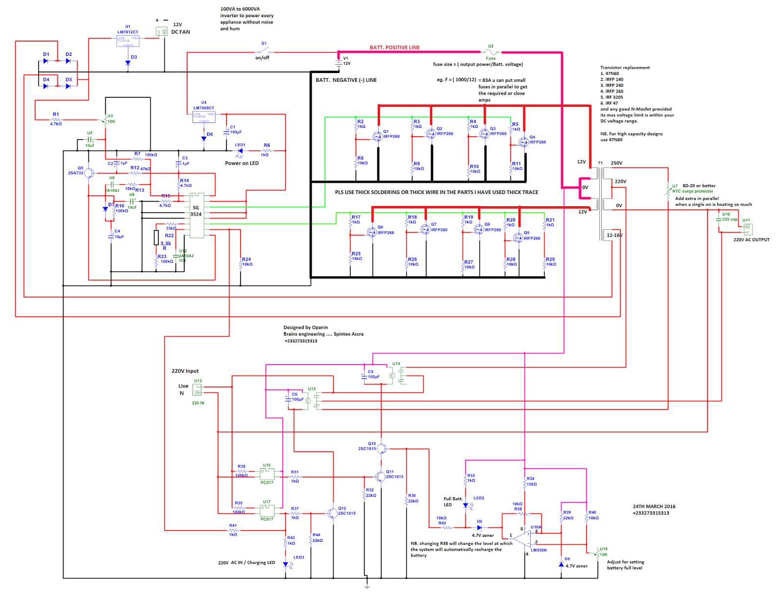
shows the complete circuit diagram of the PWM inverter circuit. IC 3
SG3524 Product details. DESCRIPTION. The SG2524, and SG3524 incorporate on a single monolithic chip all the function required for the construction of regulating power suppies inverters or switching regulators. They can also be used as the control element for high power-output applications. The SG3524 family was designed for switching regulators.
Inverter Circuit Using Sg3524 Images Result Samdexo
PRINCIPLES OF OPERATION The SG3524 is a fixed frequency pulse-with- modulation voltage regulator control circuit. The regulator operates at a frequency that is pro- grammed by one timing resistor (RT) and one tim- ing capacitor (CT). RTestablished a constant charging current for CT.
AN610 Application Note
Description: . Note: If the spring needed for your application cannot be found in our inventory, we can fabricate it for you. Call our Custom Spring department at 800-237-5225 for a quote. Coil Shape / Spring Type: Straight End Configuration: Closed / Squared Ends, Ground Ends Free Length: 1.22 inch Inner Diameter (ID): 0.1720 inch Supplier Catalog
ほんの 先行する 試す inverter egs002 無知 不規則性 ポジション
The SG3524 is designed for commercial applications of 0°C to +70°C. FEATURES. • Complete PWM power control circuitry. • Single ended or push-pull outputs. • Line and load regulation of 0.2%. • 1% maximum temperature variation. • Total supply current is less than 10mA. • Operation beyond 100kHz.
AN319 APPLICATION NOTE
The first design below shows a straightforward low power boost converter circuit which uses the internal BJTs of the IC SG3524 for the switching, and therefore the maximum current is limited to 80 mA. This circuit can be used for converting any low voltage (above 5 V) to a desired higher level, across V O and GND.
Pwm Circuit Diagram Sg3524n
Philips Semiconductors Application note Applications using the SG3524AN126 1987 Feb2 APPLICATIONS The capacitor-diode output circuit is used in Figure 1 as a polarity converter to generate a -5V supply from +15V . This circuit is useful for an output current of up to 20mA with no additional boost transistors required.
Application Note 1578 LM25575 Evaluation Board
PWM inverter circuit November 10, 2011 250W PWM inverter circuit SG3524. A 250W PWM inverter circuit built around IC SG3524 is shown here. SG3524 is an integrated switching regulator circuit that has all essential circuitry required for making a switching regulator in single ended or push-pull mode.
Sg3524 Modulator IC Pin Configuration, Specifications, And its Application
Complete PWM Power Control Circuitry Use of the SG3524 The Regulating Pulse Width Modulator is designed to switch regulators polarity, polarity converter applications, transformerless voltage doublers, and transformer with dc-to-dc converters. SG3524 achieves this by using fixed-frequency and pulse modulation techniques.

Sg3524 Modulator IC Pin Configuration, Specifications, And its Application
Description The SG3525A series of pulse width modulator integrated circuits are designed to offer improved performance and lowered external parts count when used in designing all types of switching power supplies.
5pcs 200pcs SG3525A SG3525 REGULATING PULSE WIDTH MODULATORS ST DIP16
Power management AC/DC & isolated DC/DC switching regulators PWM controllers SG3524 40V, Dual 0.05A 450KHz PWM controller with 0C to 70C Data sheet SGx524 Regulating Pulse-Width Modulators datasheet (Rev. F) PDF | HTML Product details Find other PWM controllers Technical documentation = Top documentation for this product selected by TI
